We have a small Fibre Channel SAN with three servers, a switch and a dual-controller RAID enclosure. With only a single switch, we obviously couldn’t connect all servers redundantly to the RAID system. That meant, for example, that firmware updates to it could only be applied after shutting down the servers. Buying a second switch was hard to justify for this simple setup, so we decided to hook the switch up to the first RAID controller and wire a loop off the second RAID controller. Each server would have one port connected to the switch and another one to the loop.
Back in the old days, Fibre Channel hubs existed for exactly this purpose, but nowadays you simply can’t get them anymore. However, in a redundant setup, you don’t need a hub, you can simply run cables appropriately, i.e. in a daisy-chain fashion. The only downside of not having a hub, the loop going down if one server goes down, is irrelevant here because you have a second path via the switch. For technical details on the loop topology, you can have a look at documentation available from EMC.
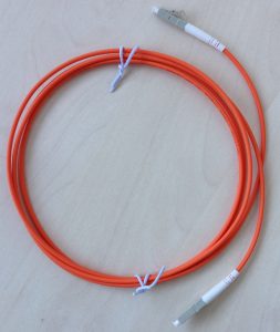
To wire your servers and RAID controllers in a fashion resembling a hub (only without the automatic bypass if a server goes down), you need simplex patch cables. These consist of a single fibre (instead of two, like you are used to) and have a connector that looks like half of a regular LC connector. You can get them in the same qualities as regular (duplex) patch cables and in single- and multi-mode as needed. They look like this:
These cables are somewhat exotic, so your usual cable dealer might not have them, but they exist and are available from specialized fiber cable dealers. As you are wiring in a daisy-chain fashion, you need one simplex cable per node you want to connect.
Once you have the necessary cables, you wire everything by connecting a cable from the output side of the FC port on the first device and connecting it to the input side of the FC port on the second device. The second device’s output side connects to the third device’s input side and so on, until you have made a full loop by connecting the last device’s output side to the first device’s input side, like this:
How can you tell the output side from the input side? Some transceivers have little arrows or have labels “TX” (output) and “RX” (input). If yours don’t, you can recognize the output side by the red laser light coming from it. To protect your eyes, never look directly into the laser light. Never connect two output sides together, otherwise you may damage the laser diodes in both of them. Therefore, be careful and always double-check.
That’s it, you’re done. All servers on the loop should immediately see the LUNs exported to the by the RAID controller.
In my setup however, further troubleshooting was required. The loop simply did not come up. As it turns out, someone had set the ports on one FC HBA to point-to-point-only and 2 Gbit/s mode. After switching both these settings to their default automatic mode, the loop went up and data started flowing. My HBAs are QLogic QLE2462 (4 Gbit/s generation) and QLE2562 (8 Gbit/s generation), and they automatically negotiated the fastest common speed they could handle, which is 4 Gbit/s. Configuring these parameters on the HBA usually requires hitting a key at the HBA’s pre-boot screen to enter the configuration menu and doing it there, or via vendor-specific software. I didn’t have access to the pre-boot configuration menu and was running VMware ESXi 6.0 on the servers. The QConvergeConsole for my QLogic adapters luckily is also available for VMware. It is not as easy to install as on Windows or Linux, unfortunately. You first install a CIM provider via the command line on the ESXi host, reboot the host and then install a plugin into VMware vCenter server.

